Saturday, 12 May 2012

3DS MAX Modelling Lego Arms

Polygon Modelling Lego Arms


Create:


(if you  don't have a .dwg of a Lego arm use vernier calipers and measure)

Create a box, 4 by 4 by 4mm. Visually align box with base of picture of the cuff.
Convert to editable polygon.


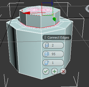
Select edge and with graphite tool, loop and connect with 2 segments at 98% until it resembles a cylinder.
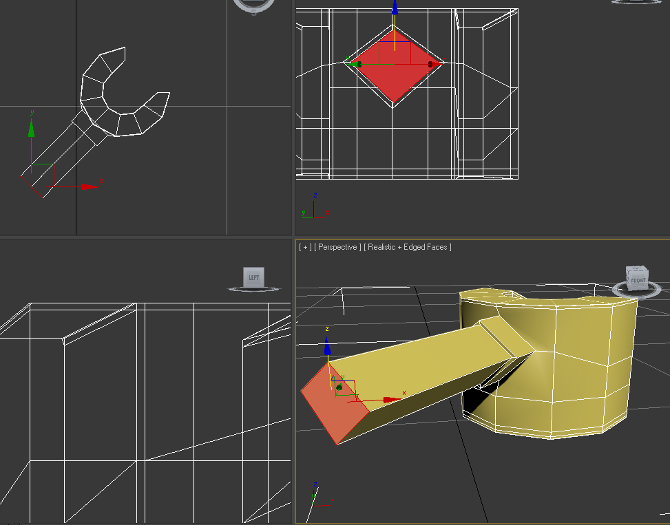
Select all polygons and scale out in line with the image and sculpt to shape. Select the top polygon and move vertically up to elbow joint ready for rotation or modification.


Add a FD222 modifier and using control points to adjust to the right angle. Apply turbosmooth to view.
Extrude and bevel. Tweak it to modify, then manually move, rotate and scale. 


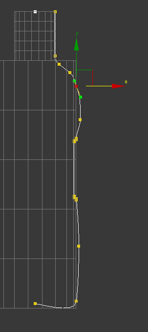
Tighten up elbow by selecting the edge, ring, loop and connect. In wire-frame, select edge, loop and move edges down to regain organic shape of shoulder. Bring in the vertices of the shoulder slightly and align with the template of the arm with the move and scale tools. Check all alignments on grid  and check the form all over the arm.


In order to see through it, change in object properties and make it see-through in poly level.


For extra refinement add extra geometry and inset polygon. Adapt to a square shape by creating another 3 by 3 rectangle which can be orientated to compare to my inset poly and align vertices.


Extrude all polygons by 0.1mm, then only selecting the central polygon extrude out to the corresponding shape of the template. 


Select edges, ring and connect to tighten geometry. To adjust further, select all poly and scale out in x+y-axis to the correct size. Select end poly and adjust and scale.


Inset another polygon on the base of the cuff and extrude upwards negatively about 5mm as measured with verniers. Add detail by edge selection as before and connect to about 98%.  


The Final Render


Friday, 11 May 2012

Modelling Lego Parts

Modelling Hands for the Ubiquitous Lego Man


Starting off with a tube, 3mm radius, 1.5mm radius and height 4mm. 8 sides and Slice is on at 270 degrees. Then in editable poly, select edge and ring. Loop and connect. 


Select edge for height definition. 3 loops at 95. Modify and Turbosmooth. 


Top view vertices, select fingertip area and move vertices to refine fingers.


In wireframe view, ctrl-select clusters of vertices and mould them down.


For the cuff, add a chamfer by selecting certain vertices and adjust in the z-axis. This has created a polygon which will be useful for extrusion of geometry. However I had to try and square it up.


Move all mid-section vertices downwards.


Select polygon for extrusion by 1mm.
Make the polygon planar as it is not perpendicular to the geometry of the hand.
Insert a polygon inside the extruded poly and extrude again.


Select edge and ring at insert edge and connect. 


Cut the triangular polygon at the insert and cut into two.


Scale out the perpendicular vertices and a large cylindrical form is gained. Connect the edges.


The result was flawed due to verticular error, I will have to redo but this is how it looks in Final Render


3ds Max Modelling A Lego Body


Polygon Modelling A Lego Body


First I begin modelling a plane over a template that I'd already created. Convert to editable polygon.


With the FD2*2*2 modifier I can scale the control points and match the lines with the template.


Selecting the edges, I can Shift and drag to the required size.


 Modified using symmetry and mirrored on the z axis.


After connecting my edges around the arm area, I delete that particular area's polygons.


After adding the Shell modifier the inside geometry is a little skewed.
Needed to Straighten Corners


Sorry, couldn't wait to see the 1st render!


Circling the arm-hole.
From the first render, the arm-hole is obviously not lego style so scaling and constraining all at the same time, I attempt to make it more circular. I can improve it further, I hope.


Now to make the hole for the neck. Extrude top four polygons 6mm high. Then choose edge, ring and connect to give it a more defined edge.
With no constraints, scale in the vertices of the neck to give it a more octagonal shape, trying to make the vertices as equi-distant as possible.


The Final Render


Friday, 27 April 2012

3d Max Lego Head

Poly-modelling a Lego Head


Starting with the previous template. Make a box and convert to editable poly and move it to surround the template exactly.


Select the top edge, ring it then connect and complete with the other side. Scale the square out into a rectangular object on the x,y axis. Turbosmooth to check. Adjust scale while showing the end result in the editable polygon modelling. Cut turbosmooth and in top level select all side edges polygons andring and connect using 2 iterations.

Select top level polygon ctrl-select all polygons on top all around and also bottom polygons and insert new inset vertex and pull amount inwards. The top inner inset polygons are extruded to form the shape. Extrude the base inset polygons to form the shape of the neck.

Select edge at the top of the neck, ring and chamfer. The top is different and selct the top edge and ring and connect with 2 iterations which are adjusted to 95%. Turbo smooth should modify it enough.

Select bottom base edge, loop and add chamfer.

Compare in front viewport to the old template and in polygon level select polygons that need to be adjusted. Select edge and loop to connect adding more definition. Pull iteration inwards to define.

When modelling the inner part of the head, Select polygons on the base and inset?
Extrude polygons with a negative amount to hollow the inside. Ring and connect . Place iterations at 95% so that the new edges Add new inset on the top of the bottom extrusion inside and extrude again negatively to reach the geometry of the top LEGO bump.


Tuesday, 24 April 2012

Modelling a Lego Head

Does this look Like a Lego Head to You? - A Lego Head


Set up in millimeters and select the line tool and draft according to specifications but do not need to be specifically accurate until you move vertices to correct profile and places in parallels in the absolute world.


Now lathe the line profile. In line level, select the vertices of the outside of the head and fillet.
Save and create a new layer and label 'head'. Make provisions for the new layers to follow ; arms, legs, body, etc...


Modelling a plastic bottle


Using Polygon Modelling


Create a background template as before using basic geometry then freeze all and make them see-through in object properties. Position on absolute zero.


Create a standard box and convert to editable poly, place on zero.
Top poly,extrude 50mm, bevel and extrude again for the neck.
Unfreeze the original object, and name the layers of poly bottle and draft. 
Hide the original. 

Ctrl-Selecting bottom edges of the base and use chamfer to smooth edges. Edge loop the shoulder ring of cylinder and also the bottom of the bottle neck and chamfer .


Check the result in the editable poly. Resembles a bottle now but needs filled out more. Remove the top polygon.
Select a shoulder edge and ring then include select all and connect.


In top level, top view select all middle vertices and scale out (x,y) to meet the outer edges of the original object.
In side view, polygon level,select down from shoulder chamfer and scale out in x,y in top view until it conforms to the original.


Select central 'label' polygons, and extrude to a negative value at a local level.Select top edge of label shoulder, loop and chamfer by 1mm. and repeat with the bottom label chamfer. Inner edge has a tighter edge chamfer of 0.1mm.


Defining the shoulder of the bottle, ctrl-select all polygons, extrude and bevel for design. Ctrl-select all bottom polygons and extrude and bevel for outer base design.


The shell modifier is adjusted to 0.5mm. The centre polygons are selected and modified with the FFD 3x3x3. Change from top level to control points. Try to change the result to FFD 5x5x5 and check the end result. Cut whichever modifier does not work to best effect.

Final render with bend modifier


Turbosmooth modifier can be set to 3 iterations for a sharper definition. 


Getting easier...?

Building a bottle (Lathe method)


LATHE METHOD


Firstly the basic shape of half of a 2d bottle is built using the line tool..

Form a cylinder which is then snapped to origins and given a radius of 25mm and height of 150mm.
Make another cylinder 12.5mm and height 30mm and snap to origin then assemble after. Then rise it up using y-axis above first cylinder.In the object property, select freeze.

Reset the grid to 10mm spacing and snap a line to this geometry, then change grid to 1mm spacing to allow for greater detail. Convert to editable spline and snap vertices to grid.

Retain 0.5mm gap of tolerance on the neck to allow for threads on the neck.


In the vertex level and the snap off, refine the geometry. Check and adjust fillet radius on the curvature on the neck. Add the concave curvature on the base.


In order to add the label placement, I refined the geometry and applied bezier corners to the line. Then it was time to remove the frozen object template.


After choosing the Lathe modification I aligned it by selecting 'Min'.


 Checking it in its rendered form, I noticed it was inside out, so I checked 'Flip Normals'.


Time to add the Shell modifier, zero for the outer amount and bearing in mind dimensions from the bottle 0.5mm for the inner amount.
As you can see the bottle surface has a few lumps and bumps, so this can modified by scrolling down the hierarchy in the modify panel. ( see below)


Smoother Render


 Now for the neck of the bottle.
Create a helix of 12.5mm with 3 turns. Then return to absolute zero.

Now I have to create shape of a 3d helix with the line tool. After adjusting the hierarchy of the line shape, snap shape to helix.


With the helix selected, go to loft and get shape now selecting the line shape.


 Modify the screw ridge using deformation of twist and scale to smooth the beginning and end of the helix ridge unit. Attach both components.


  Finally the bottle is rendered using turbosmooth on it and the 3d helix.  


What will I do next......